Search filter
137 results found
TSA 325 NT Manual
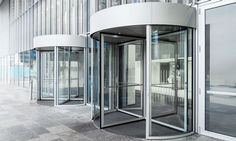
… Manual revolving door system for three- or four-leaf doors

Manual revolving doors
… Manual revolving doors ensure quiet, elegant and simple access to your building. They provide a needs-based solution when visitor numbers and passage clearances are in the lower range.
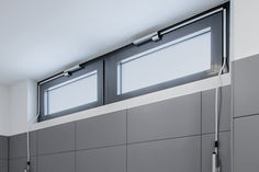
Manual fanlight openers
… manual fanlight openers provide fresh air. Thus, natural ventilation is simple and effective, also with closed main windows. Fanlight windows make rooms brighter.

Manual trigger switch
… manual release of hold-open systems

TSA 355 Manual door
… Manual revolving door system for three- or four-leaf doors

TSA 355 Manual door
… manual revolving door system TSA 355 Manual really comes into its own.

Movable glass partitioning walls
… Manual sliding wall systems offer you "mobile" flexibility for room partitioning. To open the glass partition walls, the glass elements are simply pushed together and elegantly stacked on the side.
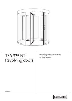
User manual TSA 325 NT revolving doors
… User manual TSA 325 NT Table of contents Supplied system … Burglar-resistant o RC2 Manual revolving door o M Underfloor drive o UFA With automatic positioning device o P Manual night-time closer o NV Automatic revolving door o A Automatic night-time closer o ANV Servo revolving door o S Internal manual night-time closer o INV All-glass o GG Internal automatic night-time closer o IANV Example: TSA 325 NT A3 NV BO = revolving door TSA 325 NT automatic drive with … leaves, with manual nighttime closer and break-out function … About these instructions About these instructions Warning notices Warning notices are used in these instructions to warn you of personal injury and property damage. XX Always read and observe these warning notices. XX Observe all measures marked with the warning symbol and warning word. Warning symbol Warning word Meaning CAUTION Danger to persons. Non-compliance can result in minor to medium injuries. Further symbols and illustrations Important information and technical notes are highlighted to explain correct operation. Symbol Meaning means “important note”; information about avoiding property damage means “additional Information” The user's attention should be drawn to important addition information. There is no danger to persons or property, but it is particularly useful to read the additional information carefully. XX … TSA 325 NT General safety notices Carefully read and abide by this user manual before commissioning the door. Always observe the following safety instructions: XX Make sure that the relevant accident prevention regulations and standard EN 16005 are observed. XX Observe any relevant additional national and European directives. XX Operating, maintenance and repair conditions specified by GEZE must be observed. àà Maintenance and repair work may only be performed by properly trained personnel authorised by GEZE. The protective conductor must be connected. àà Only trained, GEZE-authorised personnel may open the cover. àà GEZE shall assume no liability for damage caused by unauthorised changes to the system. àà The door system is solely suitable for use in entrances and interior areas of pedestrian traffic in commercial plants and public areas. àà The owner is responsible for safe operation of the system. If safety equipment is misaligned, causing it to no longer fulfil its intended purpose, further operation is no longer permissible. Inform the service technician immediately. àà In accordance with Machine Directive 2006/42/EC and EN 16005, a safety analysis must be performed and the door system identified in accordance with CE Identification Directive 93/68/EEC before the door system is commissioned. àà If there are any glass breakages (ceiling, leaf or drum wall), put the door out of use immediately and use suitable measures to prevent anyone entering the area (e.g. barrier tape). Notify a service technician. àà The door may stop unexpectedly if a safety function is triggered. It is possible that persons may walk into a stopped door leaf and hit it. àà If possible, the glass on the drum wall and side-hung leaf must be labelled at eye level through appropriate measures, to prevent persons from running into it. àà When switching over to night mode, the operator must ensure that no persons have been trapped in the door system. … mm. àà To ensure user safety, sufficient ambient lighting must be available. àà The setting for the revolving speed of the door system must be adjusted to the expected users of the system. It may be necessary to reduce the speed. àà Persons may stand in front of and inside the door system only to pass from one area to another area. àà In general, no one may stand on the roof of the door system. … Intended use The door system is solely suitable for use in entrances and interior areas of pedestrian traffic in commercial plants and public areas. Make sure the door system is used for this purpose during operation. Heed the following points when using the door system: XX Make sure that the electrically powered turnstile is not accelerated manually. XX Adapt the walking speed of the door system. XX Make sure that the opening is large enough for entering and leaving the door system. XX Do not stand still in the door system or change directions. XX Ensure sufficient distance to the drum wall and the side-hung casement. XX Do not stand still in the direct vicinity of the door entrance or exit. XX Do not enter the door carrying bulky objects or pushing a trolley (e.g. shopping trolley). XX Make sure children are always accompanied when they enter the door system. XX Keep children at play away from the door system. XX Keep animals on a short lead or carry them. The door system must be used for the intended purpose so that the revolving door safety sensors do not unexpectedly slow or stop the door system in operation. In certain conditions, changing weather conditions (wind, snow, rain, bright sunshine) can cause brief interruptions or standstill of the door system. This is not a fault, rather it is to guarantee user safety. … TSA 325 NT Explanation Rubber strip on the right post of the door system. When the rubber strip is pressed, this triggers a stop of the door system. After the rubber strip is released, the drive restarts independently after a set pause time. Rubber strip on the bottom leaf profile. When the rubber strip is pressed, this triggers a stop of the door system. After the rubber strip is released, the drive restarts independently after a set pause time. Rubber strip on the exterior vertical door leaf profile. When the rubber strip is pressed, this triggers a stop of the door system. After the rubber strip is released, the drive restarts independently after a set pause time. Optional; sticker on the door leaf when using doors with break out door fittings in emergency exit systems. Optional; use with revolving doors with a diameter over 3,000 mm. The safety sensor reduces the revolving speed when the door leaf approaches a person or triggers a stop of the door leaf. GEZE door variants Door variant Manual doors Manual doors with speed limiter Manual doors with automatic positioning device Servo doors Fully automatic revolving doors … Special feature Doors without safety function, exclusively for manual use The max. speed of the revolving door is limited by a safety mechanism in the door. Once it has been passed, the manual door is moved motor-driven to its initial/end position at very low speed. The programme switch must be set to the manual mode of operation. Increased comfort compared with a manual door thanks to automatic starting of the turnstile with radar movement detector. In order to reach walking speed, the turnstile can be overridden by hand. After the door has been passed, it revolves slowly to the final position. The speeds are limited. The programme switch must be set to the manual mode of operation. Activation via movement detector. Electromechanical drive with two pre-adjustable speeds. The revolving movement starts automatically. Special feature The drum walls do not have a frame at the top or bottom and the door has a glass roof. The drum walls have a frame and the door has a glass roof. The side-hung casements can be broken out in any position by pressing the outer edge of the leaf. When a leaf is broken out, the drive is switched off immediately. The door leaves can be engaged again by hand. Then the door continues revolving until it reaches its end position. Burglar-resistant fitting system tested in accordance with DIN EN 1627 1630. Special version of the night-time closer, drum walls and roof. TSA 325 NT … What does the door do? The door begins to revolve. The door slows down to a standstill if necessary. As soon as the passing leaf comes nearer than the preset danger distance, the door slows down to a standstill. The door slows down to a standstill. The door slows down to a standstill. Additional door functions In addition to the keypad programme switch, various additional functions control the door manually via switches or push buttons. Which switch/push button? Emergency stop switch Key push button of the keypad programme switch Contact sensor “Authorised” (e.g. outside key push button) Activation button Push pad Key switch for night-time closer … 99). The arrow keys are used for entry. The factory setting is 00 (released). Operating status Automatic TPS-KDT Explanatory notes All the connected pulse generators are active in the “Automatic” operating mode. Revolving speed and time delay can be set. When activated by a movement detector the door accelerates to the set automatic speed, continues to revolve at this speed and stops in the target position after a preset number of sectors. The following special functions are possible in the “Automatic” operating mode: Summer operation The turnstile stands still without activation. When activated for the first time, the revolving door accelerates to automatic speed. After that the revolving door revolves at the automatic speed for a number of sectors that can be set and then slows to the run-on speed. The revolving door revolves at the slow speed for a set time delay and then stops in the next target position. This operating mode is particularly suitable for creating an welcoming atmosphere. If the time delay is set to endless, the revolving door revolves permanently. Winter operation The turnstile stands still without activation. When activated, the revolving door accelerates to the automatic speed. After that the revolving door revolves at the automatic speed for a number of sectors that can be set and then stops in the target position. In “Automatic” operating mode, alteration between summer and winter operation can be affected by simultaneously pressing the buttons and . If winter operation is selected, the LED “Winter” is illuminated in the TPS-KDT. Exit only Manual Night mode … Activation of push pad (optional) A switch with a wheelchair symbol is located on the door. When this switch is activated, the door brakes and revolves at the set disabled access speed. This speed is specified for the set number of sectors. In the “exit only” operating mode the door is only activated via the internal movement detector, then revolves for a set number of sectors at automatic speed and then stops again in the target position. The turnstile can be rotated freely in manual operation. If no further functions are set, the “Manual” operating mode is identical with the “Off” operating mode. The following options can be set: àà An automatic positioning device returns the door to the target position at slow speed after passing has been completed. àà Safety devices can be activated. àà The speed limiter can be activated. àà Prescribed mode of operation for revolving doors with automatic positioning device and servo revolving doors. The following options for locking can be built into the system in order to lock it in the “Night” operating mode: No locking If the revolving door does not have a locking function, it can be revolved manually in the “Night” operating mode. TSA 325 NT Operating status Night mode Operation TPS-KDT Explanatory notes Manual locking A rod locking can be used as a manual locking element. A contact used to monitor the locking operating mode is installed. Unlock Lock XX Disengage lock. XX Disengage lock. XX Unlock leaf. XX Lock leaf. XX Engage lock. XX Engage lock. The leaf locking mechanism may also function as mirror-inverted for the all-glass version (AG). To lock the door manually: XX Select the “Night” operating mode at the keypad programme switch. The Night LED flashes on the TPS-KDT. The door revolves automatically to the locking position. XX Lock the locking device manually. The Night LED switches to continuous light. Unlocking the door manually: XX Unlock the locking device manually. The Night LED of the TPS-KDT switches to flashing. XX Set the desired operating mode on the TPS-KDT. The LED indicates the operating mode. Locking device with disc brake A disc brake can be used to lock the revolving door. When the power supply is interrupted, the brake is opened. The revolving door can then be revolved manually. It is not suitable for a revolving door with break-out function. Locking the door: XX Select the “Night” operating mode on the TPS-KDT. The Night LED flashes on the TPS-KDT. The door revolves automatically to the locking position. The disc brake is activated. The Night LED switches to continuous light. Unlocking the door: XX Select the desired operating mode on the TPS-KDT. The disc brake is released. The new operating mode is active and is displayed on the TPS-KDT. … Operation Operating status Night mode TSA 325 NT TPS-KDT Explanatory notes Electromagnetic lock One or two electromagnetic locks can be used to lock the revolving door. A locked door remains locked when the power fails. An unlocked door remains unlocked when the power fails. In the case of a power failure the lock can be unlocked by means of a built-in battery. XX Select the “Night” operating mode at the keypad programme switch. The door moves to the end position and locks automatically. Option: Revolving door suitable for use in escape and rescue routes. Only with the break out variant (BO) with a separate key push button for locking. XX During the slow movement into the end position, press the key operated button and keep it pressed. The door locks automatically in the end position. XX Release the key operated button again. XX In order to unlock the door, activate the key operated button and switch on the desired operating mode at the button programme switch. Access via the contact sensor authorised (only at revolving doors suitable for use in escape and rescue routes): XX Operate the authorised contact sensor (I think). The door revolves once. XX In order to lock the door hold the authorised contact sensor authorised until the door has locked automatically. Locking in the event of a power failure In order to avoid the danger of persons being locked in, the revolving door may not be entered when the locking bolts are lowered and may only be turned further from the outside. A special locking switch is required for locking and unlocking. Locking with night-time closer The revolving door can be locked with a single leaf or double leaf night-time closer manual or automatic). Manual night-time closer: The procedure is identical to manual locking. Automatic night-time closer: XX Select the “Night” operating mode on the TPS-KDT. The door revolves automatically to the locking position. XX In order to lock the night-time closer, activate the key push button and hold it until the nighttime closer is closed and locked. XX In order to open the night-time closer, activate the switch and hold it until the night locking system is open. XX Select the desired operating mode on the TPS-KDT. When locking the door, the operator must ensure that no persons have become caught in the door system. Off … XX In the “Off” operating mode the motor is switched off and the door can be freely revolved manually . This operating mode is especially suitable for maintenance and cleaning of the door. All activation devices are switched off. Locking/unlocking (optional) For a description of locking/unlocking the door, see Section … No mains voltage Behaviour in an emergency CAUTION! Danger of injury caused by crushing! The door leaf may only be snapped into place by trained personnel. XX When re-engaging the breakout leaf, ensure that your fingers do not become stuck on the inner leaf edge. If a revolving door suitable for escape and rescue routes is used, the operator must ensure that the door really is unlocked after it has been unlocked. The door can be stopped via the emergency stop switch and moved manually. Revolving doors with break out system (BO) can be opened in any position by pressing the outer edge of the leaf (< 220 N), clearing a suitable escape route. The drive is switched off immediately after the leaf has been broken out and the turnstile can be revolved manually. … No mains voltage XX If the mains voltage fails (e.g. power failure), check the on-site safety fuse first. State Reaction No mains voltage In “Night” operating mode, the door remains locked as long as a disc brake was not used. In other operating modes, the door coasts to standstill and stops. The door starts again in the previously set operating mode. The door can be revolved manually providing it was not locked. Mains voltage available again Door leaves revolve if there is no active power supply … What to do if...? Problem Door revolves very slowly Door does not revolve Cause Floor area soiled Remedy XX Interrupt power supply. XX Clean the affected floor area. XX Remove obstruction and check door manually for smooth Obstruction in travel path movement. Mobile safeguarding device XX Clean safety sensor. is interrupted or misaligned XX Check the setting of the optical safety sensors. XX Revolve the door manually, remove visible obstacles. If no obstaScraping on floor, other mechanical impediment cles are visible, notify a service technician. XX Check movement detector. Movement detector misXX Notify a service technician. aligned or defective XX Select another operating mode. “Night”, “Off” operating mode “Exit only” operating mode XX Select “Automatic” operating mode. Door is locked manually XX Unlock the door. No mains voltage XX See chapter 5, “No mains voltage”. XX Unlock emergency stop switch. XX XX Engage the door leaf again by hand and wait for the door system to start up. Select another operating mode. No mains voltage XX See chapter 5, “No mains voltage”. Obstruction in travel path XX XX Remove the obstacle. Notify a service technician. Change to the “Manual” operating mode and check the movement force manually. If the revolving force is too high, notify a service technician. Check locking in the “Night” operating mode. Unlock the door manually and notify a service technician. Activate the key push button, repeat the unlocking process. XX Activate key switch. XX Request servicing. XX See chapter 6, “Fault messages on the programme switch TPS-KDT”. XX Put the door out of operation immediately and take suitable measures to prevent anyone entering the door (e.g. barrier tape). Notify a service technician. Emergency-stop switch pressed Door leaf has been broken out (BO variant) Door only revolves manually “Off” operating mode Door always revolves only a bit further XX XX Door does not unlock or lock Locking defective (in case of automatic locking) Key push button not activated Programme switch cannot Programme switch be operated is blocked Programme switch is defective Fault messages displayed at Fault in the door system programme switch Glass break Impact on pane (door leaf/drum wall) XX XX XX 12 TSA 325 NT Cleaning and maintenance Carry out a reset/delete the fault memory Use key or to change to the mode of operation OFF (see Section
(PDF | 374 KB)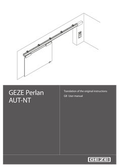
User manual Perlan AUT-NT
… User manual … Intended use The PERLAN AUT-NT sliding door drive is designed for the automatic opening and closing of the sliding leaves. The PERLAN AUT-NT sliding door drive is suitable for use in dry rooms in private areas. The PERLAN AUT-NT sliding door drive may not be used at fire or smoke protection doors and in a hazardous (Ex) area. The PERLAN AUT-NT sliding door drive may not be used to open and close vertical sliding leaves. Any other use than the proper use, such as permanent manual operation, as well as all changes to the product are impermissible. … GEZE Perlan AUT-NT Safety instructions Thoroughly read and abide by this user manual before commissioning the door. In addition, always observe the following safety precautions: àà The prescribed mounting, maintenance and repair work must be performed by properly trained personnel authorised by GEZE. àà The country-specific laws and regulations are to be observed during safety-related tests. àà GEZE shall not be liable for injuries or damage resulting from unauthorised modification of the system. àà GEZE shall not be liable if products from other manufacturers are used with GEZE equipment. àà Only original GEZE parts may be used for repair and maintenance work. àà The connection to the power supply must be made by a professional electrician. Perform the power connection in accordance with DIN VDE 0100-610. àà The electrical installation at the customer has to have an all-pole power disconnector that can be secured reliably against reactivating (e.g. lockable switch with at least … Terms Term Drive sides at 1-leaf systems Drive sides at 2-leaf systems Contactors Statement The side of the track on which the drive unit is located, is usually the closing direction of the sliding leaf The side of the track on which the drive unit is located, is usually the opening direction of the sliding leaf Button, switch or motion detector for actuating the sliding door drive. Actuation function in the "Automatic" operating mode Contactor with switch Button for opening and closing the sliding leaf. Actuation function only in the "Automatic" function operating mode. The sliding leaf is opened automatically when the button is first pressed and closed again automatically when the button is pressed the second time. The function can be activated during commissioning by parameter configuration. Push & Go If the sliding leaf is pressed manually out of the closing position during an activated Push & Go function in the "Automatic" operating mode, the sliding leaf opens automatically. Stop Self-locking switch with which immediate stopping of the sliding door drive can be triggered in case of danger. The sliding door drive remains in its current position until the user releases the stop switch again, thus terminating the stop situation. … . XX Replace the motor and/or controller if necessary. Self-test – driver fault recog- The power driver no longer outputs a fault – nition defective message Hardware – encoder fault The encoder is not connected correctly or XX Check the encoder connection. XX Replace the motor or controller. is defective XX Replace the power pack. Hardware – voltage impos- The supply voltage lies outside the perXX Replace the controller if necessible missible range sary. Memory – RAM defective A defect has been recognised in the RAM XX Replace the controller. Memory – ROM defective The programme memory has been changed or is defective Memory – EEPROM defec- The data memory is defective tive A fault state is indicated by flashing codes of the two LEDs on the controller: First the red LED flashes rapidly, then it lights up continuously for approx. 20 seconds. During these 20 seconds the green LED flashes in accordance with the fault code x times. The cycle repeats until the user resets the fault. Example: Green LED flashes
(PDF | 1 MB)
User manual Automatic sliding doors
… User manual DCU1-NT, DCU1-2M-NT, DCU1, DCU1-2M Contents … For the user … Symbols and illustrations Warning notices Warning notices are used in these instructions to warn you of personal injury and property damage. XX Always read and observe these warning notices. XX Observe all the measures that are marked with the warning symbol and warning word . Warning symbol Warning word Meaning WARNING Danger to persons. Non-compliance may result in death or serious injuries. CAUTION Danger to persons. Non-compliance can result in minor to medium injuries. Further symbols and illustrations Important information and technical notes are highlighted to explain correct operation. Symbol Meaning means “important note”; information about avoiding property damage means “additional Information” The user's attention should be drawn to important addition information. There is no danger to persons or property, but it is particularly useful to read the additional information carefully. XX Symbol for an action: This means you have to do something. XX If there are several actions to be taken, keep to the given order. Escape and rescue route; means the sliding door cannot be operated in escape and rescue routes Not an escape and rescue route; means the sliding door cannot be operated in escape and rescue routes BO … BO Break-out; means BOthat the door leaves and side panels are equipped with a break-out function BO No break-out; means the function is not possible for break-out doors Product liability In accordance with the manufacturer's liability for their products as defined in the German “Produkthaftungsgesetz” (Product Liability Act), the information contained in this user manual (product information and proper use, misuse, product performance, product maintenance, obligations to provide information and instructions) is to be noted and followed. Failure to comply releases the manufacturer from his statutory liability. … Special cases In certain cases, deviations from the information given in this user manual may occur. Examples: àà Special wiring àà Special function settings (parameters) àà Special software XX Please contact the service technician responsible for further information. … Terms Term Activation device inside (KI) Explanation Push button, switch or movement detector for activating the door drive. The activation device is located within the room enclosed by the door. Activation function in the “Automatic” and “Exit only” modes of operation. The activation device does not have any function in the “Night/Locked” and “Off” mode of operation. Activation device outside (KA) Push button, switch or movement detector for activating the door drive. The activation device is located outside the room enclosed by the door. Activation function in the “Automatic” mode of operation. The activation device does not have any function in the “Exit only”, “Night/Locked” and “Off” mode of operation. Activation device authorised Access control function (for example key switch or card reader) used by authorised (KB) persons to activate the door drive. The activation function is active in the “Automatic” “Exit only”, “Night/Locked” and “Off” modes of operation. Opening safety sensor (SIO) Presence detector (e.g. active infrared light sensor) for protecting the swinging range of the door in the opening direction. The sensor secures the secondary closing edge. Closing safety sensor (SIS) Presence detector (e.g. active infrared light sensor) for protecting the swinging range of the door in the closing direction. The sensor secures the main closing edge on the inside and outside. Emergency stop Self-locking switch with which immediate stopping of the door drive can be triggered in case of danger. The door drive remains in its current position until the user releases the emergency stop switch again, thus terminating the emergency stop situation. Emergency lock When the emergency lock is triggered, the door is closed and locked. The activations and safety devices are deactivated during the closing process. Reset Push button for restarting the drive after the operating voltage has been switched on or after a fire alarm has been terminated. When the push button is pressed, the self-retention integrated in the drive is activated, causing the drive to be activated. … For the user Fundamental safety precautions Carefully read and abide by this user manual before commissioning the door. Always observe the following safety instructions: àà Operating, maintenance and repair conditions specified by GEZE must be observed. àà The commissioning, mandatory installation, maintenance and repair work must be performed by experts authorised by GEZE. àà Any relevant additional country-specific and European directives must also be observed. àà Use in dry rooms only. àà The intervals for safety-related testing are to be complied with based on the country-specific regulations. àà The connection to the mains voltage must be made by a professional electrician. àà No changes may be made to the system without prior agreement from GEZE. àà GEZE shall assume no liability for damage caused by unauthorised changes to the system. àà The owner is responsible for safe operation of the system. àà Have a service technician check the safe operation of the system at regular intervals. àà Should safety devices be misaligned, thus preventing them from fulfilling their intended purpose, further operation is not permissible. The service technician must be informed without delay. àà Make sure that the safety stickers are attached visibly to any glass leaves and are in a legible state. àà Protect the programme switch against unauthorised access. àà Danger of injury by sharp edges on the drive when removing the cover àà Danger of injury by parts hanging down àà This appliance can be used by children aged from … years and above and persons with reduced physical, sensory or mental capabilities or lack of experience and knowledge if they have been given supervision or instruction concerning use of the appliance in a safe way and understand the hazards involved. àà Children shall not play with the appliance. àà Cleaning and user maintenance shall not be made by children without supervision. … .1 Standard functions (automatic mode of operation) In normal operation, the door is automatically opened and closed. What happens? An activation device (push button, switch or movement detector) is triggered. What does the door do? Door opens and closes again. Closing safety sensor is triggered when the door is open. Door remains open. Closing safety sensor is triggered when the door is closed. Door remains closed. Closing safety sensor is triggered while the door is closing. Door opens again. Opening safety sensor is triggered when the door is closed. Door remains closed. Opening safety sensor is triggered while door is opening. Door stops. Opening safety sensor is triggered while door is opening. The door does not stop until the reduced opening width (escape route width) has been reached. A person moves toward the opened door and a movement detector is Door remains open. activated. A person moves toward the closing door and a movement detector is Door opens again. activated. Door contacts an obstruction when opening. Door contacts an obstruction when closing. BO BO Door stops, waits and attempts to move to the open position at a reduced speed three times. Then the door closes again. Door reopens immediately, waits the hold-open time and then closes at a reduced speed. Door leaf or side panel is broken out. Door remains in the current position and can be moved manually. Door leaf or side panel is latched in again. Door functions again in the last mode of operation. BO BO 11 Description … Explanation A fault 07 (fire alarm) is displayed at the programme switch. Door closes immediately with dampened closing speed and remains closed. Changing the mode of operation is not possible. Door can only be opened manually. Normal operation is restored by pressing the reset switch. The reset switch can be reached by opening the drive cover. See Chapter 5, No mains voltage. Behaviour at smoke alarm (Slimdrive SL-RD) Operating status Smoke alarm Normal operation Mains power failure … DCU1-NT, DCU1-2M-NT, DCU1, DCU1-2M Locking/unlocking if there is no mains voltage Locking type Toothed belt locking Measures Locking only makes sense when the door is closed. Locking with drives with built-in rechargeable battery àà If the door is to be locked and this door is the only point of access: XX Push the door closed manually from the inside. XX Push the locking pin. XX Activate the (inner) authorised activation device until initialisation of the drive is completed. DPS or TPS indicates Night/Locked mode of operation. Door opens – leave the building – door closes – locks again and switches off. Unlocking from the outside with drives with built-in rechargeable battery XX Activate the (outer) authorised activation device until the drive is initialised and the door starts to open. Door opens – door closes – locks again and switches off. Unlocking from the inside with drives with built-in rechargeable battery: XX Activate the (outer) authorised activation device until the drive is initialised and the door starts to open. Door opens – door closes – locks again and switches off. Unlocking with drives without built-in rechargeable battery (only possible from the inside) XX Push the door to the desired locking position and push/slide the locking pin (9, Chapter … ). The door leaves are unlocked and can be opened manually. Rod locking, Lock A and folding door lock Locking is only possible when the door is closed. Locking with drives with built-in rechargeable battery If the door is to be locked and this door is the only point of access: XX Push the door closed manually from the inside. For sliding door with rod locking: XX Lock using an Allen key through the drill hole in the cover in the indicated direction of rotation. For sliding doors with Lock A (see also installation instructions “Automatic hook bolt lock Lock A”): Manual locking: XX Insert a tool with approx. Ø … mm at the bottom into the slot of the main closing edge/side screen profile and press the lock upwards. Manual unlocking: XX Insert a tool with approx. Ø … mm at the bottom or top of the slot in the main closing edge/side screen profile and lock in the indicated direction of movement. With folding door and folding door locking: XX Unlock with a hollow set-screw through the recess in the left post profile in the indicated direction of rotation until the door leaves can be pushed opened by hand. Locking for SL-BO Locking is only possible at a closed door. Locking with drives with built-in rechargeable battery If the door is to be locked and this door is the only point of access: XX Push the door closed manually from the inside. XX Push the locking pin. XX Activate the (inner) authorised activation device until initialisation of the drive is completed. DPS or TPS indicates Night/Locked mode of operation. Door opens – leave the building – door closes – door locks again and switches off. Unlocking from the outside with drives with built-in rechargeable battery XX Activate the (outer) authorised activation device until the drive is initialised and the door starts to open. Door opens – door closes – door locks again and switches off. Unlocking from the inside with drives with built-in rechargeable battery XX Activate the (inner) authorised activation device until initialisation of the drive is completed. Unlocking with drives without built-in rechargeable battery (only possible from the inside) XX Push the door to the desired locking position and push the locking pin (9, Chapter … ). The door leaves are unlocked and can be opened manually. After the mains voltage has been restored, the (locked) door automatically switches to the “Night/Locked” mode of operation. 19 Fault messages DCU1-NT, DCU1-2M-NT, DCU1, DCU1-2M … , Behaviour at fire alarm Door does not unlock or lock Locking defective Door does not close Closing safety sensor (SIS) interrupted or misaligned Obstruction in travel path Unlock/lock the door manually: XX Check lock in the “Night/Locked” mode of operation. If the locking is defective: XX Notify a service technician. XX Clean the closing safety sensor (SIS). XX Check settings of light curtain. XX Remove obstruction and check door leaf for ease of movement. XX Check movement detector. Movement detector triggers constantly XX Select a different mode of operation. “Hold open”, “Off” mode of operation No mains voltage (e.g. power failure) See Chapter 5, No mains voltage. Programme switch cannot be operated Programme switch is blocked Programme switch is defective Fault messages displayed Fault in the door system at programme switch Activate key switch. Enter password. XX Request servicing. See Chapter 6, Fault messages XX XX Carry out a reset/delete the fault memory àà With keypad programme switch: XX Use key or to change to the mode of operation “Off” (see Chapter
(PDF | 2 MB)